Thank you for visiting nature.com. You are using a browser version with limited support for CSS. To obtain the best experience, we recommend you use a more up to date browser (or turn off compatibility mode in Internet Explorer). In the meantime, to ensure continued support, we are displaying the site without styles and JavaScript.
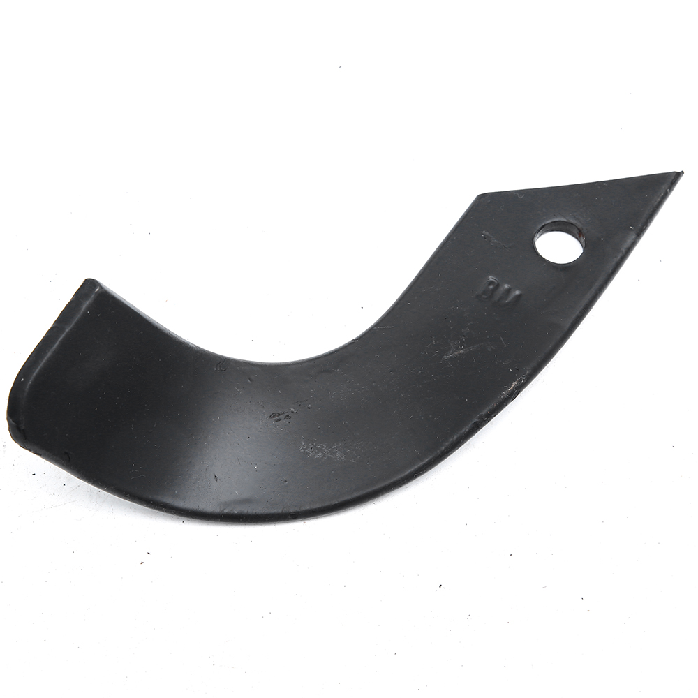
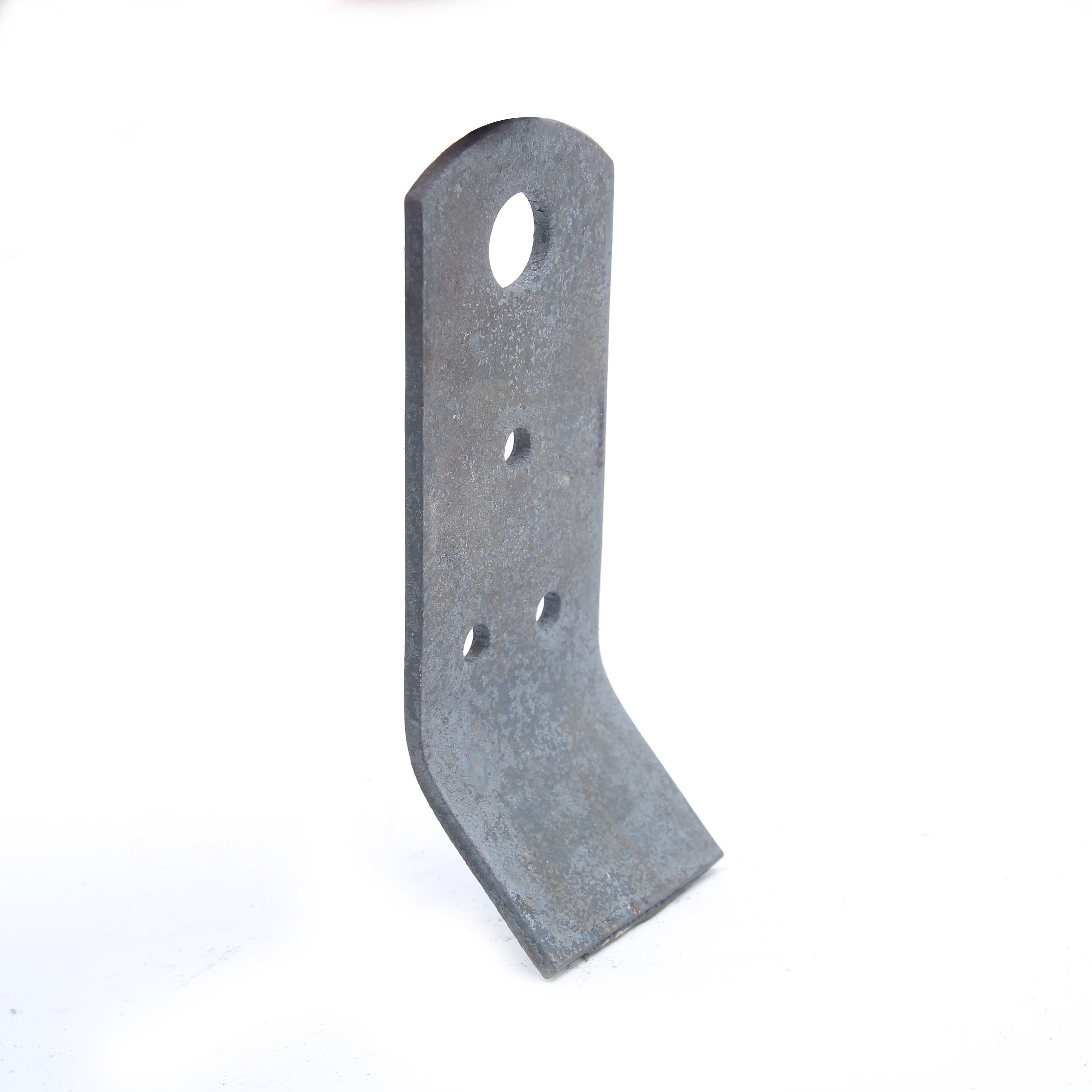
Scientific Reports volume 13, Article number: 5757 (2023 ) Cite this article Flail Blades
This report analyzes the problem of complex soil movement patterns under the action of coupled forces, such as tension and shear, in agricultural processes and aims to improve the accuracy of contact parameters used in discrete element simulation studies of rototiller-soil interactions. This study focuses on the soil of Shihezi cotton field in the 8th division of Xinjiang and investigates the rotating tiller roller as a soil-touching component of tillage machinery. A combination of simulations and physical testing is used. We perform angle of repose tests and use edge detection, fitting, and other image processing methods to automatically, quickly, and accurately detect the soil accumulation and angle calibration of the contact parameters with soil particles. Additionally, soil slip tests are conducted to calibrate the contact parameters between the soil and the rotary blades. Optimization is achieved based on orthogonal simulations and the Box-Behnken response surface method using physically measured values as the target. A regression model of the stacking angle and rolling friction angle is established to determine the optimal combination of simulation contact parameters: between soil and soil, the recovery coefficient is 0.402, static friction coefficient is 0.621, and rolling friction coefficient is 0.078; between soil contact parts and soil, the recovery coefficient is 0.508, static friction coefficient is 0.401, and rolling friction coefficient is 0.2. Furthermore, the calibration parameters are selected as contact parameters for the discrete element simulation. By combining the above two simulation methods to analyze and compare the simulation process of cutting soil from rototiller roller parts to rototiller single blade parts, we obtained the changes in energy, cutting resistance, and soil particle movement at different depths of the soil cutting process. Finally, the average cutting resistance was used as an index for validation in the field tests. The measured value is 0.96 kN and the error of the discrete element simulation is 13%. This demonstrates the validity of the calibrated contact parameters and the accuracy of the simulation, which can provide a theoretical reference and technical support for the study of the interaction mechanisms between of tillage equipment parts and soil, as well as the design and optimization of these interactions in the future.
Santosh Korav, Dharam Bir Yadav, … Eman A. Mahmoud
Martin Hartmann & Johan Six
Xin Li, Dong Wu, … Wenju Zhang
Mechanized tillage and soil preparation technology is the most basic mechanized technology for farm work. It is also an important tool to improve the quality of arable land1,2. Notably, the rotary cutter roller is in direct contact with the soil, which affects the quality and efficiency of operation at all times. Thus, the accuracy of cutting simulations need to be improved for calibrating and optimizing the soil contact parameters.
With the development of computer-aided engineering design, numerical simulation methods have been continuously applied to various fields, including agricultural engineering3,4. The main advantage of numerical simulations is their ability to produce fast predictions without the need for multiple field tests5,6. In recent years, discrete element (DEM)7,8 and Smoothed Particle Hydrodynamics(SPH)9 methods have shown unique advantages in revealing the interaction mechanisms between components of agricultural machines and soil particles. Makange10 introduced bonding elements between DEM particles in the contact model to simulate the actual cohesive soil and studied the horizontal and vertical forces and soil disturbance of a plow at different speeds and depths. Kim11 modeled agricultural soils and predicted tractive forces for different tillage depths, calibrated the DEM soil model using a virtual blade shear test, and performed field tests with a prediction accuracy of 7.5% for tractive forces. AIKINS12 integrated the hysteretic spring model and linear cohesion model to calibrate the static and rolling friction factors of high-viscosity soils and verified the accuracy of the parameters calibration by comparing them with trenching tests. MILKEVYCH13 established a model of soil displacement caused by the interaction between soil and components in the weeding process based on the discrete method, and the simulated and measured tests of soil displacement were consistent. Uggul and Saunders14 simulated the interaction between the plate-type plow and the soil using the DEM method, and the results were compared to experimental tests, analytical draught force results, and furrow profile measurements. The results revealed that DEM has the potential to predict soil-mouldboard plow interaction with reasonable accuracy. Li15, Lu16, Kang17, and Niu18 performed soil cutting simulations involving smooth particle dynamics to obtain the change law of soil motion and cutting energy. The structural parameters were optimized to reduce power consumption, and finally, the correctness of the simulation was verified using the soil flume test. Liu19 compared SPH and FEM simulation methods in the soil-cutting process. The simulation results were similar when there was no mesh distortion in the early stage. With mesh distortion, the FEM algorithm produced errors. Thus, the FEM-SPH coupling method was proposed to take advantage of the respective benefits, and the feasibility of this method was verified.
DEM is a numerical calculation method for analyzing complex dynamic discontinuous mechanical discrete systems20. It can effectively simulate the microscopic and macroscopic movement between materials and has advantages in the study of agricultural machinery. Moreover, FEM has high efficiency and accuracy in calculating the mechanical deformation of continuum media21,22, whereas SPH has a greater advantage in simulating large deformation, large damage, and high nonlinearity23. Therefore, this paper uses physical and simulation tests, as well as experimental optimization design, to calibrate soil-related contact parameters and uses DEM and FEM-SPH coupling methods to conduct cutting simulation analysis. Among them, the special feature and novelty of the paper is that the two simulation methods are integrated to realize the simulation of soil cutting dynamics of rotary tiller roller and Single rotary tillage knife respectively, and the simulation accuracy is improved by calibrating the contact parameters, and ultimately, to investigate the laws of complex soil motion and energy consumption changes of components during cutting.
The 3D model of the rotary cutter roller is modeled using SOLIDWORKS software. The structure of the rotary blade adopts the national standard of the "rotary tillage machinery knife and knife seat". The blade material is 65Mn spring steel. The 3d model of the simulation test is based on the rotary blade, knife holder, and roller axis of the rotary tillage component (model 1GQK-125). The assembly model of the rotary blade roller is shown in Fig. 1.
The models of the hose pump.
The soil was used from a 0–50 cm depth in the Wugong Village, Shihezi City, Xinjiang Province, North China. The soil texture configuration mainly consisted of loose soil. The soil density was measured using a five-point sampling method using a ring knife (100 cm3) and an electronic balance (0.01 g), and the average density was 1250 kg/m3. The average moisture content of the soil was 9.63%, measured using the TDR300 soil moisture meter. The average soil solidity at 40 cm depth was 2.14 MPa, measured using an SC900 soil solidity meter. For other parameters, refer to reference24 and obtain soil and other material parameters of 65 Mn steel as shown in Table 1.
Calibration experiments were conducted according to the Box-Behnken optimization method in the Design-Expert software, building discrete element contact models and soil particle templates. Calibration was performed using the soil rest angle test, and the soil slip simulation was used to measure the accumulation angle and sliding friction angle values. Optimization of the simulation was aimed at predicting the actual measurement results of the physical experiments. Then, we obtained the group solution that is closest to the measured value and use that as the optimal combination for calibration.
Soil is a complex combination of soil particles, water, and gas, and there are various types of chemical bonds. The existence of water in soil causes adhesion between soil particles, thus forming particle aggregates. To accurately simulate the mechanical stresses on soil particles under mechanical action, it is necessary to establish a suitable contact mechanics model.
The plastic deformation of materials have been used to create a delayed contact elasticity model based on the type of soil being evaluated25,26 (hysteretic spring contact model, HSCM). The model allows the plastic deformation behavior to be added to the contact mechanics equations, such that the particles behave elastically under a predefined stress. The physical generalization of the interparticle contact relations and the force–displacement relations are shown in Fig. 2.
In Fig. 2, Oa and Ob are the spherical center positions of two particles, Ra and Rb are the radii of two particles (mm), δn is the normal overlap of particle collision (mm), δ0 is the residual overlap between particles (mm), Fs and Ft are the normal contact force and damping force (N), fs and ft are the tangential contact force and damping force (N), and μ is the friction coefficient.
The HSCM normal force FN is calculated using the following equation:
where, K1 and K2 are the loading and unloading stiffnesses, respectively. Then, δn is the normal overlap and δo is the residual overlap.
The loading stiffness K1 is related to the yield strength of each material involved in contact. The relationship between Y1 and Y2 is expressed as follows:
where, R* is the equivalent radius of two contact particles, and Y1 and Y2 are the yield strengths of particles a and b, respectively.
The following expression for the recovery factor e can be used with K2 to determine K1
The amount of residual overlap is updated at each time step according to the following law:
The main energy dissipation mechanism depends on the difference in spring stiffness between the loaded and unloaded phases.
By consulting the Chinese soil database from the experimental soil samples, the particle size and shape of the soil was obtained. Discrete metasoftware EDEM was used to create soil particles that match the soil used in the experiment based on a simplified spherical model. A total of 3 soil particles were modeled, as shown in Fig. 3. (a) Single-ball model, with a radius of 6 mm; (b) two-sphere model, with a single sphere radius of 6 mm and a combined radius of 8 mm; (c) linear three-sphere model, with a single sphere radius of 5 mm and a combined diameter of 9 mm.
Three soil discrete particles of different shapes and sizes will be randomly generated in the particle plant of EDEM software to simulate different soil particles in real soil.
We established a soil accumulation angle simulation test to calibrate the contact parameters between soil particles (Fig. 4a), waiting for all the soil particles to move to the bottom of the funnel to form a stable accumulation, and after stabilization, we measure the angle to use as the calibration value compared with experimental data.
Next, we performed physical tests of the angle of repose (Fig. 4b). The soil accumulation angle measurement was automated using image processing methods such as MATLAB image binarization, segmentation, inversion, and Canny operator edge detection and fitting27. The automatic measurement of the specific image processing process is shown in Fig. 5. To ensure the accuracy of the measurement, the test was repeated 20 times to take the average value, and the final measurement result was 34.98°, whose value was used as the target value for the response surface method.
Image processing process for automatic measurement of stacking Angle.
The contact parameters between the soil and rototill component material (65Mn steel) were calibrated using soil slip simulation tests (Fig. 6a). To control the test condition more precisely and measure the corresponding test results, we used the sliding friction angle obtained when some of the soil particles (> 30%) slide down the inclined plate as a basis for calibrating the test. At the same time, we conducted the physical test of soil slip (Fig. 6b), which was repeated 20 times to take the average value. The final test result is 26.98°, which was used as the target value for the response surface method.
We used the Box-Behnken method in Desin-expert software for the experimental design of the soil accumulation angle and slip test simulation parameter calibration. The physical experiment results of the stacking angle (39.98°), the simulation scale (small scale), and the material stacking density (1250 kg/m3) are entered into the generic EDEM material model database (GEMM) to obtain the relevant parameters. The ranges were jointly determined according to the literature28,29,30,31: soil-to-soil recovery coefficient X1 (0.2–0.6), rolling friction coefficient X2 (0.14–0.4), and static friction coefficient X3 (0.3–0.7). According to the literature32,33 the ranges between soil and rotary cutter (65 Mn) were also determined: recovery coefficient X4 (0.28–0.6), rolling friction coefficient X5 (0.04–0.2), and static friction coefficient X6 (0.3–0.6).
The above-mentioned X1, X2, X3, X4, X5, and X6 were selected as the test influencing factors, using soil-soil rest angle Y1 and soil-plate (65 Mn steel) sliding friction angle Y2 as evaluation indexes. We implemented a total of 17 sets of experiments. The factor level codes of the simulation tests are shown in Table 2, and the results of the soil rest angle and slip simulation tests are shown in Tables 3 and 4, respectively.
Considering the tool cutting mode and boundary condition processing requirements, the soil trough model is designed as a 1200 mm × 600 mm × 250 mm uncovered rectangular body, and a virtual surface is established above it. We set the gravitational acceleration along the Y-axis to 9.81 m/s and generated 1.8 × 10⁶ soil particles to fill the trough and simulate the rototill soil-cutting environment. At the same time, we defined the rotary cutter with the same forward speed v = 800 m/h and rotational speed, n = 110 r/min, and counterclockwise rotation to cut the soil, as conducted in the subsequent field test. The established model of the rototill-soil interaction is shown in Fig. 7.
DEM model of the rototill-soil interaction.
Combining the advantages and disadvantages of the FEM and SPH methods, the SPH algorithm is used in the larger deformation area, i.e., the soil part, and the FEM algorithm is used for the smaller deformation area, i.e., the rotating tiller part. This method can maximize the advantages of both methods to provide greater accuracy and efficiency of the computational solution.
The K-file was imported from ANSYS software after meshing and using LS-Prepost finite element software to modify the keywords. Then, we converted all the nodes of the soil finite element model into corresponding SPH particles. During the conversion process, we ensured that the number of meshes during meshing is the same as the number of generated SPH particles,the conversion result is shown in Fig. 8.
Among them, Lagrange-type single-point integration algorithm was used to divide the soil finite element mesh with the edge length of 10 mm. Fixed constraints were added to the bottom and sides of the soil model, and penalty factor of sliding interface was defined as 0.2, dynamic friction factor was 0.18, and static friction factor was 0.2. Meanwhile, contact mode between rotary tiller and soil was set as point-surface erosion contact. After all boundary conditions were set, K-files were saved and imported into LS-dyna Solver for calculation and solution.
Here, we chose the MAT No. 147 (*MAY_FHWA_SOLID) soil model material with a modified Mohr–Coulomb criterion34, which adds deformation rate, water content effect, and cell deletion. The yield surface for this model F is expressed as:
where, P is the pressure (Pa),φ is the angle of internal friction (°), J is the 2nd invariant of the pressure bias tensor, K(\(\theta^{2}\) ) is a function of the tensor plane angle, c is the cohesive force, and ahyp is the yield surface similarity of the modified Mohr–Coulomb yielding criterion.
The analysis of variance (ANOVA) was performed using Design-Expert software, which shows that the P-test for the regression coefficients of the soil accumulation angle and sliding friction angle models in the response surface regression model is significant, whereas the misfit term is not significant. Additionally, the goodness-of-fit of the two regression models are 0.91 and 0.92. Furthermore, ANOVA was obtained for the soil accumulation angle and sliding friction angle trials, as shown in Table 5. The established model correlates with practical experiments and can predict the experiment well. From the F-test of the recovery coefficient, the dynamic friction and static friction coefficients between soil particles can be obtained, as well as between the soil and rotary cutter (65Mn steel), using the regression equations of soil rest angle Y1 and soil sliding friction angle Y2 as follows:
where, X1, X2, X3 is the coefficient of recovery, coefficient of dynamic friction and coefficient of static friction between soil and soil. X4, X5, X6 is the restoration coefficient, dynamic friction coefficient and static friction coefficient between soil and rotary tillage knife.
The magnitudes of the regression coefficients of each factor of the model are shown in Table 2, revealing the significance of each factor on the resting angle and sliding friction angle of the soil: the regression terms X2, X3, X6, X42, and X62 exhibited highly significant effects, and X2X3 and X5X6 exhibited significant effects. We also observed the order of significance of each factor on the soil rest angle and sliding friction angle models, with X3 > X2 > X1 and X6 > X5 > X4, respectively.
From the results obtained using the response surface method, the optimal contact parameters between soil particles and between the soil and rotary cutter (65Mn steel) were determined, as shown in Table 6. To verify the accuracy of the calibrated contact parameters, we implemented the experimentally calibrated soil contact parameter values in the EDEM software. The simulation was repeated 10 more times, and we measured the average value to obtain the rest angle and soil rolling friction angle of 35.7° and 29.23°, respectively. Compared with the resting angle and sliding friction angle of the soil measured by physical tests, the errors with the actual physical tests were 2.01% and 2.5%, respectively, and the cone of the soil pile obtained from the simulation test of the soil rest angle was similar to the cone of the physical test. From the measurement results and profiles, the calibrated soil parameters enable the discrete element simulation model to match the real soil particles more closely.
In the EDEM post-processing, the soil particles and the rotary cutter movements were indicated using color. The knives contact soil particles and increase their speed, and the cut soil exhibits upward movement along the -cutting direction, as shown in Fig. 9.
As the rotary cutter gradually enters the soil, the positive cutting edge of the cutter first contacts the soil, and then the soil is crushed along the direction of the cutter by the upper extrusion of the cutting edge on the side, and the disturbed area of the soil gradually increases (Fig. 9a–c). Then, the soil is disturbed further by the dual action of the side cutting edges and the edges of the multiple rotary tillage blades, which appeared along the blades counterclockwise rotation direction, until the knife roller completely plunged into the soil, the soil disturbance area reached a maximum (Fig. 9d). This simulation also reveals the longitudinal pushing effect of the knife roller on the soil during rototilling. Finally, when the knife roller gradually leaves the soil, the soil disturbance area gradually decreases (Fig. 9e,f).
The working resistance of the rotary blade is shown in Fig. 10. During the cutting process, the cutting resistance is 0 when the rotary blade is not in contact with the soil. With the rotation of the roller shaft, the rotary blade gradually contacts and penetrates the soil, and the cutting resistance gradually increases. With the blade rotating continuously, the rotary blade contact soil area and soil cutting volume are increased, and its plowing depth also gradually becomes larger. After reaching the maximum plowing depth value, the corresponding blade roller resistance also reaches the maximum.. Moreover, the blade roller rotates 720° within 1 s, so the cutting resistance of the rotary blade roller presents two periodic changes.
To study the energy changes in the process of soil cutting for the rotary blade and the soil microscopic movement, we simplified the rotary cutter by selecting a single rotary cutter part for modeling the simulation, which shortened the simulation time and improved the simulation accuracy. The simulation process is shown in Fig. 11.
Cutting simulation process of FEM-SPH simulation method.
The variation of energy consumption (internal energy) of the soil cutting operation using a single rotary cutter is shown in Fig. 12. With increasing contact area between the soil and the cutter, the internal energy consumption of the rotary cutter gradually increases, and when the rotary cutter leaves the soil, the total energy consumption remains at a stable level (i.e., stops increasing).
Internal energy change of single rotary blade during cutting.
To display the movement of soil particles more intuitively. We selected different soil surfaces, including the top layer (particle A; Node: 128544), middle layer (particle B; Node:125758), and deep layer (particle C; Node:120172). Then, we obtained the velocity curves of one SPH particle at each depth, as shown in Fig. 13. In the cutting process (50–1000 ms), the order of soil particle movement speeds from large to small were surface particles, middle particles, and deep particles. When the rotary cutter leaves the soil, the soil particles still have speed, but the degree of movement gradually decreases, which is consistent with the analysis shown in Fig. 10 and the actual working conditions of a rotating curved blade.
Velocity of soil particle motion at different layer depths.
To verify the accuracy of the calibrated contact parameters and simulations, a field test was conducted (May 2022 in Wugong village, Shihezi city, Xinjiang). The soil had an average soil firmness of 2.16 MPa and a water content of 10.64%. The TN654 tractor was used for tilling, and the test equipment included a rotary tillage device, a mechanical tachometer (range of 0–400 r-min-1), and an NJTY3 dynamic telemetry system. Images of the measuring equipment and field tillage test are shown in Fig. 14.
The working resistance and energy consumption were measured by wireless telemetry, adopting the technical solution of supporting power output shaft integrated torque sensor and frameless three-point suspension traction sensor. We set the motion parameters to be consistent with discrete element simulation for the field tests. That is, the forward speed v = 1100 m/h, rate n = 120 r/min. The measured average cutting force was 0.92 kN, revealing an error of 15% for the discrete element simulation. The cutting force in practice was higher than the simulation value because the actual operation was subject to additional consumption caused by roots, debris, and other friction and wear in the soil.
We established regression models for soil rest angle and sliding friction angle, which revealed goodness-of-fit values of 0.91 and 0.9, respectively. We also obtained the magnitude and order of significance of the effects of the three factors and interactions, revealing the following order: sliding friction coefficient > static friction coefficient > recovery coefficient.
We used Canny operator edge detection and other image processing methods to achieve automatic measurement of the soil accumulation angle, effectively improving efficiency and accuracy. Using the response surface optimization method, we obtained the optimal combination of contact parameters between soil: recovery coefficient of 0.48, rolling friction coefficient of 0.56, and static friction coefficient of 0.24. The optimal combination of contact parameters between the soil and tool were also obtained: recovery coefficient of 0.5, rolling friction coefficient of 0.1, and static friction coefficient of 0.31. To verify the accuracy of the calibrated simulated contact parameters, the obtained optimal contact parameters were subjected to soil accumulation angle simulation tests again, and the errors compared with the physically measured values were 2.01% and 2.5%, which were within the acceptable range, indicating that the calibrated contact parameters have improved reliability.
Using the calibration parameters as the contact parameters in the DEM simulation, we can effectively and intuitively observe the soil breaking process, changes in the soil disturbance area, and obtain the curves of the periodic change of cutting force for the cutter.
From the field tests, using cutting resistance as the index to verify the simulations, the average cutting force of the measured knife roller was 0.98 kN, and the cutting force of the cutting process was higher than the simulation value. The average cutting force error of 13% was observed for the DEM simulation. Furthermore, the two rotary soil effect is almost the same for experimental and simulated results.
This work can function as a theoretical reference and technical support for determining the interaction mechanisms between soil and equipment components, such as disc harrows and plowshares, as well as assisting in the design and optimization of related equipment.
The datasets used or analyzed during the current study are available from the corresponding author on reasonable request.
The numerical model software during the current study are available from the corresponding author on reasonable request.
Song , Q.M. Mechanization technology of cultivated land. in Selected Papers of the 14th National Conference on Agricultural Machinery Maintenance (2010).
He, J., Li, H. W., Chen, H. T., Lu, C. Y. & Wang, Q. J. Progress in research on conservation tillage technology and implements. Trans. Chin. Soc. Agric. Mach. 49, 1–19 (2018).
Zhao, H., Huang, Y., Liu, Z., Liu, W. & Zheng, Z. Applications of discrete element method in the research of agricultural machinery: A review. Agriculture 11, 425 (2021).
Zeng, Z. W., Ma, X., Cao, X. L., Li, Z. H. & Wang, X. C. Current status and outlook of the application of discrete element method in agricultural engineering research. Trans. Chin. Soc. Agric. Mach. 52, 1–20 (2021).
Jirigalantu, L. X., Mi, X., Liu, K. & Tang, Y. Development of a parameterized mechanical model of a chisel-edge grating ruling tool. Precis. Eng. 50, 388–392 (2017).
Rehman, T. U., Mahmud, M. S., Chang, Y. K., Jin, J. & Shin, J. Current and future applications of statistical machinelearning algorithms for agricultural machine vision systems. Comput. Electr. Eng. 156, 585–605 (2019).
Jun, G. et al. Design and simulation for seeding performance of high-speed inclined corn metering device based on discrete element method (DEM). Sci. Rep. 12, 19415 (2022).
Article CAS PubMed PubMed Central ADS Google Scholar
Barr, J. B., Ucgul, M., Desbiolles, J. M. A. & Fielke, J. M. Simulating the effect of rake angle on narrow opener performance with the discrete element method. Biosyst. Eng. 171, 1–15 (2018).
Zhu, L. X. Finite Element Simulation and Optimization of Rotary Tillage Knife Based on SPH Algorithm (Southwest University, 2012).
Makange, N. R. Prediction of cutting forces and soil behavior with discrete element simulation. Comput. Electr. Eng. 179, 105848 (2020).
Kim, Y. S., Siddique, M., Kim, W. S., Kim, Y. J. & Dem Lim, R. G. simulation for draft force prediction of moldboard plow according to the tillage depth in cohesive soil. Comput. Electr. Eng. 189, 106368 (2021).
Kaaa, B. et al. Determination of discrete element model parameters for a cohesive soil and validation through narrow point opener performance analysis. Soil Tillage Res. 213, 105–123 (2021).
Viktor, M., Munkholm, L. J., Ying, C. & Tavs, N. Modelling approach for soil displacement in tillage using discrete element method. Soil. Tillage. Res. 183, 60–71 (2018).
Ucgul, M. & Saunders, C. Simulation of tillage forces and furrow profile during soil-mouldboard plough interaction using discrete element modelling. Biosyst. Eng. 190, 58–70 (2019).
Li, S. T., Chen, X. B., Chen, W. & Zhu, S. P. Soil-cutting simulation and parameter optimization of handheld tiller’s rotary blade by smoothed particle hydrodynamics modelling and Taguchi method. J. Clean. Prod. 179, 55–62 (2018).
Lu, C., He, J., Li, H. W. & Wang, Q. J. Simulation of soil cutting process by plane blade based on SPH method. Trans. Chin. Soc. Agric. Mach. 45(8), 134–139 (2014).
Kang, S. L. Finite Element Analysis and Optimization of Microtiller Tool (Chongqing University of Technology, 2015).
Niu, P. Research on Power Consumption and Vibration Characteristics of Electric Microtiller Operation (Southwest University, 2020).
Liu, Y. C., Wang, X. S., Feng, M. & Zhang, H. H. Soil cutting simulation and research based on SPH/FEM coupling algorithm. J. Agric. Mech. Res. 39, 21–27 (2017).
Asaf, Z., Rubinstein, D. & Shmulevich, I. Evaluation of link-track performances using dem. J. Terramech. 43, 141–161 (2006).
Tsuji, T., Nakagawa, Y., Matsumoto, N., Kadono, Y., Takayama, T., & Tanaka, T. 3D DEM simulation of cohesive soil-pushing behavior by bulldozer blade. J. Terramech. 49, 37–47 (2012).
Karmakar, S., Ashrafizadeh, S. R. & Kushwaha, R. L. Experimental validation of computational fluid dynamics modeling for narrow tillage tool draft. J. Terramech. 46(6), 277–283 (2009).
Lampropoulos, A.D., & Manolakos, D.E. Application of SPH method for modeling of metal extrusion process. Comput. Part. Mech. 9, 1–17 (2021).
He, X. N., Zhang, X. J., Zhao, Z., Shang, S. Q. & Wang, D. W. Design and experiments of oil soya bean lowering resistance excavation device based on discrete element method. Trans. Chin. Soc. Agric. Mach. 52(12), 124–133 (2021).
Ucgul, M., Fielke, J. M. & Saunders, C. Three-dimensional discrete element modelling (DEM) of tillage: Accounting for soil cohesion and adhesion. Biosyst. Eng. 129, 298–306 (2015).
Walton, O. R. & Braun, R. L. Stress calculations for assemblies of inelastic speres in uniform shear. Acta Mech. 63, 73–86 (1986).
Gonzalez, R. C. & Woods, R. E. Digital Image Processing 3rd edn. (Prentice-Hall Inc, 2007).
González-Montellano, C., Ramírez, Á., Gallego, E. & Ayuga, F. Validation and experimental calibration of 3D discrete element models for the simulation of the discharge flow in silos. Chem. Eng. Sci. 66, 5116–5126 (2011).
Yu, Y. & Henrik, S. Discrete element method simulation of properties of a 3D conical hopper with mono-sized spheres. Adv. Powder. Technol. 22(3), 324–331 (2011).
Toschkoff, G. et al. Spray models for discrete element simulations of particle coating processes. Chem. Eng. Sci. 101, 603–614 (2013).
Wu, S. et al. DEM simulation of particle size segregation behavior during charging into and discharging from a paul-wurth type hopper. Chem. Eng. Sci. 99, 314–323 (2013).
Yu, Y. & Henrik, S. Experimental and DEM study of segregation of ternary size particles in a blast furnace top bunker model. Chem. Eng. Sci. 65, 5237–5250 (2010).
Song, S. L., Tang, Z. H. & Zheng, X. Calibration of discrete element parameters of post-tillage soil model for cotton fields in Xinjiang. Trans. Chin. Soc. Agric. Eng. 37, 63–70 (2021).
Reid, J. D.,Coon, B. A., Lewis, B. A., Sutherland, S. H. & Murray, Y. D. Evaluation of LS-DYNA Soil Material Model 147. (Fhwa-Hrt-04-094 2004:85) (2004)
This work was supported by Construction Project of Demonstration Platform for National New Materials Production & Application—Demonstration Platform for Production & Application of Materials on The Agricultural Machinery Equipments (grant number TC200H01X-5).
College of Mechanical and Electrical Engineering, Shihezi University, Beisi Road, Shihezi, 832003, Xinjiang, China
Xiongye Zhang, Lixin Zhang, Xue Hu, Huan Wang & Xuebin Shi
You can also search for this author in PubMed Google Scholar
You can also search for this author in PubMed Google Scholar
You can also search for this author in PubMed Google Scholar
You can also search for this author in PubMed Google Scholar
You can also search for this author in PubMed Google Scholar
Investigation: X.Z., X.H. Methodology: X.Z. Software: H.W., X.Z. Experimental studies: X.Z., X.H., X.S. Data acquisition and analysis: X.Z., X.H., H.W. Writing—original draft: X.Z. Writing—review and editing: X.H., X.Z. Manuscript final version approval: L.Z. Project administration: L.Z. Funding acquisition: L.Z. All authors agree to publication of the manuscript.
The authors declare no competing interests.
Springer Nature remains neutral with regard to jurisdictional claims in published maps and institutional affiliations.
Open Access This article is licensed under a Creative Commons Attribution 4.0 International License, which permits use, sharing, adaptation, distribution and reproduction in any medium or format, as long as you give appropriate credit to the original author(s) and the source, provide a link to the Creative Commons licence, and indicate if changes were made. The images or other third party material in this article are included in the article's Creative Commons licence, unless indicated otherwise in a credit line to the material. If material is not included in the article's Creative Commons licence and your intended use is not permitted by statutory regulation or exceeds the permitted use, you will need to obtain permission directly from the copyright holder. To view a copy of this licence, visit http://creativecommons.org/licenses/by/4.0/.
Zhang, X., Zhang, L., Hu, X. et al. Calibrating contact parameters of typical rotary tillage components cutting soil based on different simulation methods. Sci Rep 13, 5757 (2023). https://doi.org/10.1038/s41598-023-32881-1
DOI: https://doi.org/10.1038/s41598-023-32881-1
Anyone you share the following link with will be able to read this content:
Sorry, a shareable link is not currently available for this article.
Provided by the Springer Nature SharedIt content-sharing initiative
By submitting a comment you agree to abide by our Terms and Community Guidelines. If you find something abusive or that does not comply with our terms or guidelines please flag it as inappropriate.
Scientific Reports (Sci Rep) ISSN 2045-2322 (online)
Maschio Tiller Blade Sign up for the Nature Briefing newsletter — what matters in science, free to your inbox daily.